Introduction
In optical lens manufacturing, alignment errors are one of the most common reasons why real-world imaging performance fails to meet design expectations. Even when high-quality optical components are used, improper alignment during assembly can significantly degrade image quality.
For applications such as machine vision, infrared imaging, microscopy, and industrial inspection, controlling alignment errors is essential for achieving reliable and repeatable performance.
This article outlines the most common optical lens alignment errors, explains how they affect image quality, and discusses practical methods to avoid them during manufacturing and assembly.
What Is Optical Lens Alignment?
Optical lens alignment refers to the accurate positioning of optical elements relative to the system’s mechanical and optical axes. Proper alignment ensures that:
- All lens elements share a common optical axis
- Axial spacing matches the optical design
- Tilt and decentration are minimized
- Performance remains stable after fixation
Alignment errors usually originate during assembly, bonding, or mechanical integration—and often cannot be corrected once the lens is fully assembled.
Common Optical Lens Alignment Errors
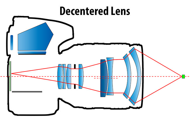
1. Lens Decentration
Decentration occurs when the optical center of a lens element does not coincide with the mechanical axis of the lens barrel.
Impact on image quality:
- Asymmetric aberrations (coma, astigmatism)
- Reduced contrast and sharpness
- Degraded performance at higher spatial frequencies
Even micron-level decentration can noticeably reduce image quality in high-performance systems.
2. Lens Tilt
Lens tilt happens when an optical element is angled relative to the optical axis.
Common causes:
- Uneven adhesive thickness
- Poor seating surfaces
- Mechanical stress during fixation
Impact on image quality:
- Field-dependent blur
- Reduced edge performance
- Increased image asymmetry
Tilt errors are especially critical in large-aperture and long focal-length lenses.
3. Incorrect Axial Spacing
Axial spacing errors occur when the distance between lens elements deviates from the design value.
Impact on image quality:
- Focus shift
- Increased spherical aberration
- Reduced field uniformity
Spacing errors often result from tolerance accumulation or improper spacer control during assembly.
4. Accumulated Tolerance Errors
In multi-element optical systems, small errors from each component can accumulate into a significant system-level issue.
Impact on image quality:
- Inconsistent performance between units
- Difficulty achieving repeatability in batch production
- Increased rejection or rework rates
This problem becomes more severe as lens complexity increases.
5. Post-Assembly Alignment Drift
Even when alignment is correct during assembly, performance can change over time due to:
- Thermal expansion
- Mechanical vibration
- Adhesive shrinkage
- Environmental stress
This is a common challenge in industrial, infrared, and high-temperature applications.

How Alignment Errors Affect Real-World Performance
Alignment errors typically lead to:
- Reduced image sharpness and contrast
- Lower consistency across the field of view
- Performance variation between production batches
- Increased system-level calibration effort
In many cases, customers experience these issues as unexplained image quality problems, even though individual optical components meet specification.
How to Avoid Optical Lens Alignment Errors
Precision Alignment and Centration Processes
High-precision alignment techniques are essential for minimizing decentration and tilt. Advanced centration and alignment processes ensure that the optical and mechanical axes are properly matched before final fixation.
Controlled Assembly Environment
Maintaining a controlled environment helps reduce alignment drift caused by:
- Temperature variation
- Mechanical vibration
- Contamination during assembly
Stable conditions improve repeatability and long-term performance.
Proper Mechanical Design for Assembly
Mechanical design plays a critical role in alignment quality. Features such as:
- Accurate reference surfaces
- Controlled fits and tolerances
- Stress-relief structures
help maintain alignment throughout the product lifecycle.
Verification After Assembly
Image quality verification after final assembly is essential to confirm alignment stability. This may include:
- Optical performance checks
- Functional imaging tests
- Third-party performance verification when required
Verification ensures that alignment quality is not assumed—but confirmed.
Why Alignment Expertise Matters When Choosing a Supplier
When selecting an optical lens manufacturer, buyers should evaluate more than design capability alone. Key questions to ask include:
- How are decentration and tilt controlled during assembly?
- What alignment processes are used for complex lens systems?
- How is consistency ensured in volume production?
- How is long-term stability validated?
Manufacturers with strong alignment expertise are better equipped to deliver lenses that perform reliably in real applications.
Conclusion
Optical lens alignment errors are one of the leading causes of image quality degradation in real-world systems. By understanding common alignment issues—and implementing precise assembly and alignment processes—manufacturers can significantly improve performance, consistency, and reliability.
As optical systems continue to demand higher precision, alignment quality becomes a key differentiator in optical manufacturing.
Work With a Precision Optical Lens Assembly Partner
We specialize in:
- High-precision optical lens assembly
- Advanced alignment and centration processes
- Infrared and industrial optical systems
- Opto-mechanical integration
If you are experiencing image quality issues related to alignment—or want to prevent them from the start—
📩 contact us today to discuss your application or request a quotation.