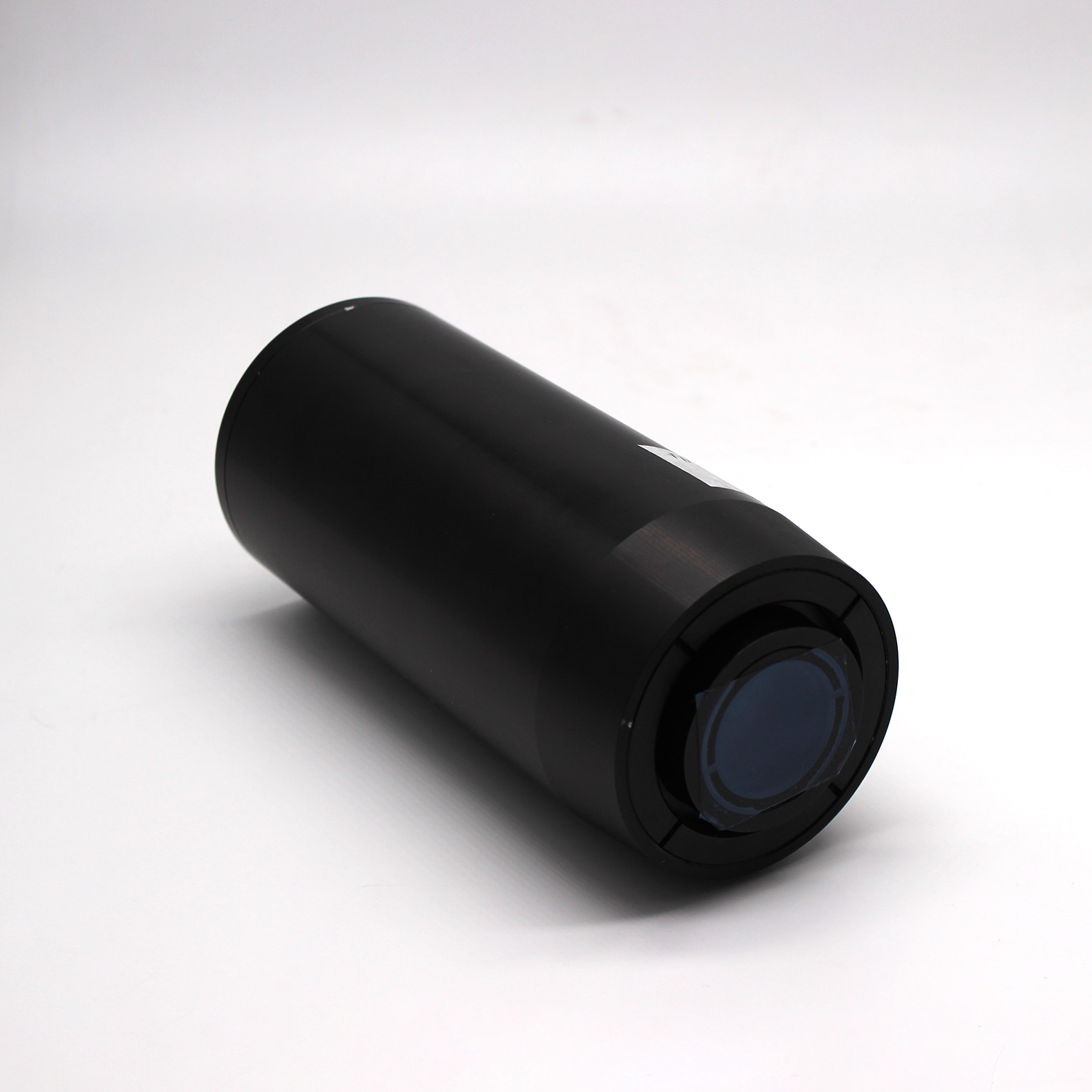
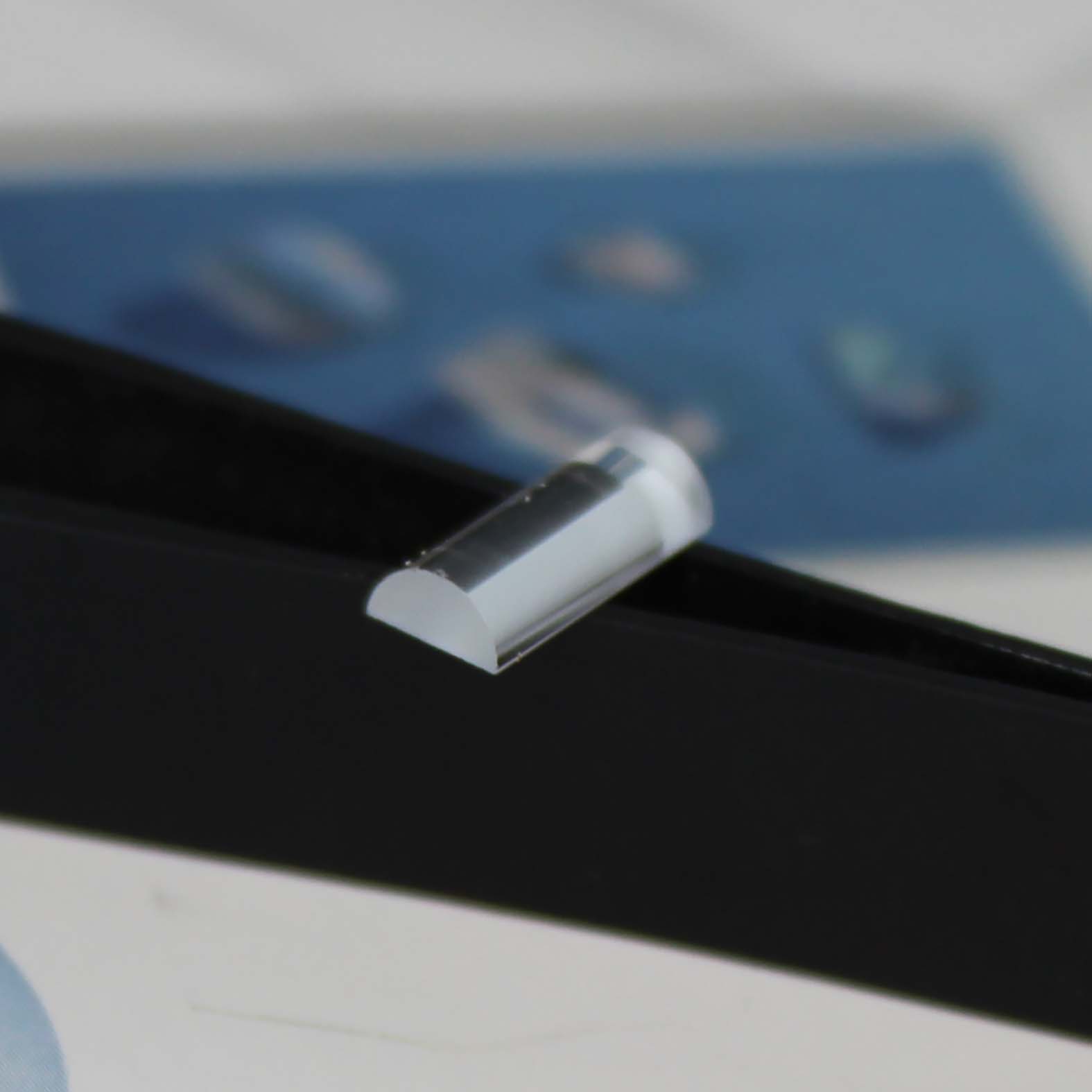
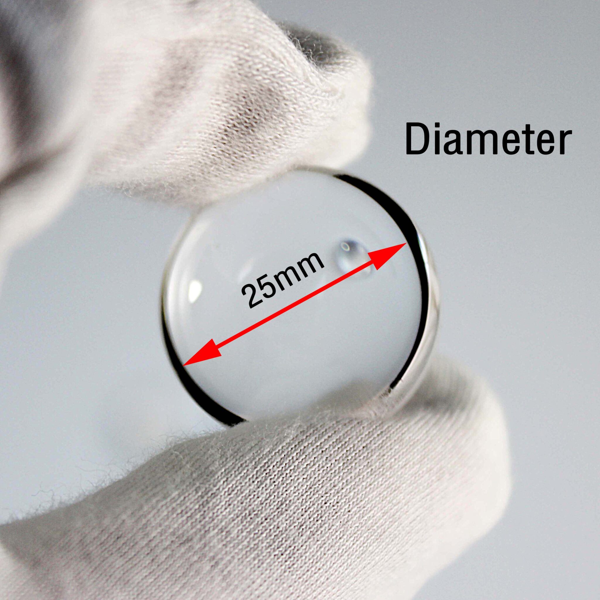
Custom AOI Optical Lens Design: From Requirement to Final Assembly
Introduction
In many AOI projects, customers first ask for a lens with a certain focal length, working distance, or magnification.
These details are important. However, they are only the starting point.
For automated optical inspection, the final image quality depends on the whole system. The lens needs to match the camera sensor, field of view, working distance, lighting, defect size, mechanical space, and inspection target.
If one part is not well matched, the system may still have problems. For example, the image may have soft edges, missed defects, unstable measurement, distortion, or repeated calibration.
Therefore, custom AOI optical lens design should not start only from a catalogue model. It should start from the real inspection need.
At VY Optics, we support custom optical lens design, optical component manufacturing, lens assembly, alignment, and optical-mechanical integration for AOI, machine vision, and industrial inspection applications.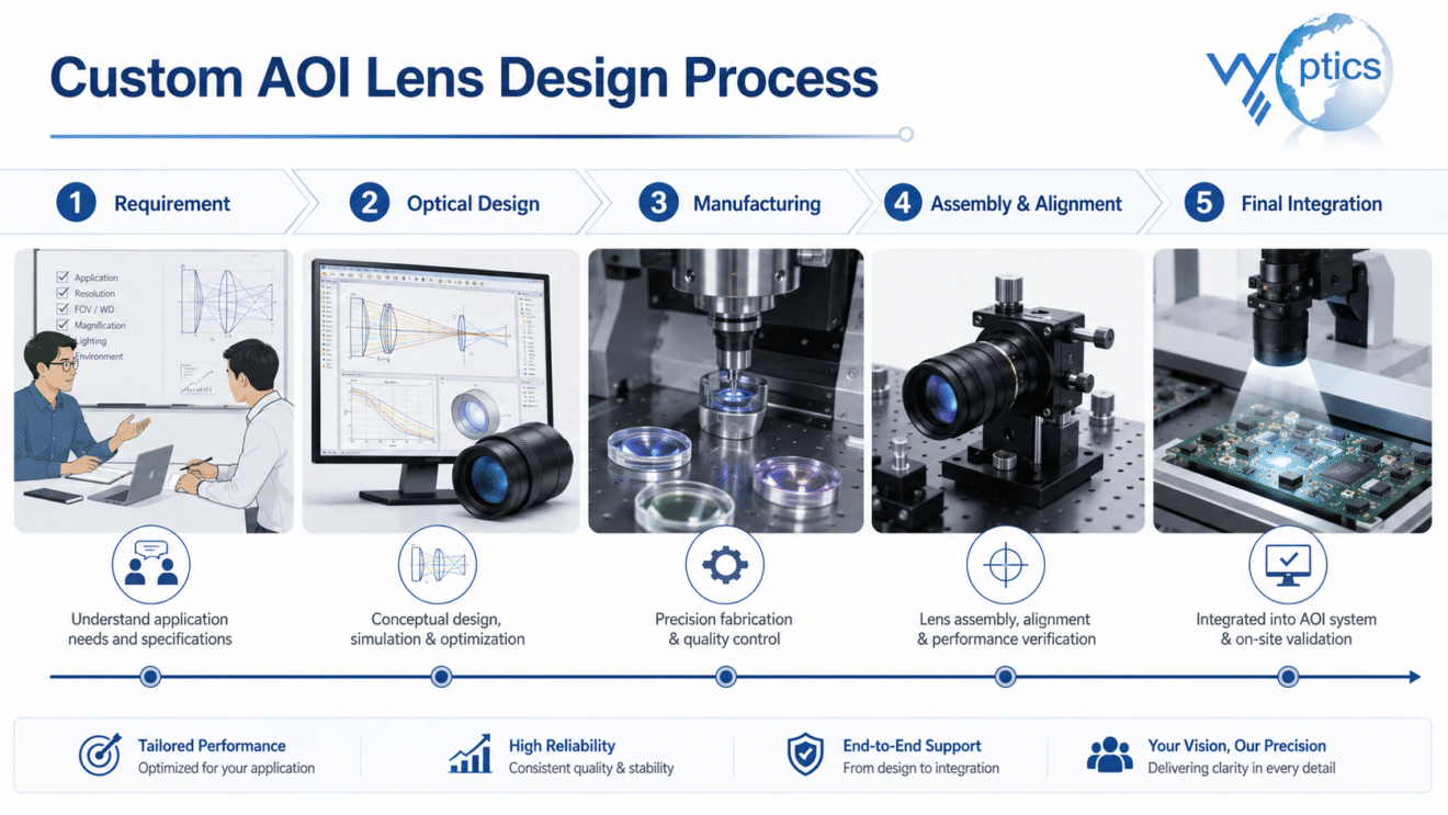
Why AOI Lens Design Starts from the Requirement
A good AOI lens is not simply a high-resolution lens.
Different AOI systems have different jobs.
For example, one system may need to detect small scratches or particles. Another system may need to inspect PCB pads, solder joints, or connector pins. In other cases, the system may need to measure hole diameter, edge distance, part position, or alignment.
Because the inspection tasks are different, the lens solutions are also different.
Before starting the optical design, we usually need to know:
- what object needs to be inspected
- the smallest defect or feature size
- whether the task is defect detection, measurement, or both
- the required field of view
- the available working distance
- the camera sensor size
- the wavelength or lighting method
- whether the image needs to stay clear from center to edge
- whether low distortion is important
- the available installation space
Once these details are clear, the lens direction becomes much easier to define.
Step 1: Understand the Inspection Target
The first step is to understand the inspection target itself.
A flat PCB surface is different from a three-dimensional connector. Wafer inspection is also different from checking a metal part with reflective edges.
In practice, the surface material, reflectivity, feature size, height change, and accuracy requirement all affect the optical design.
In some AOI and flat-field imaging projects, the system needs to observe features around 12 μm under the required camera, lighting, working distance, and optical setup.
At this level, the lens cannot only look good in the center. Edge clarity, distortion, lighting, focus stability, and assembly accuracy all become important.
For higher-magnification inspection, the requirement can be even smaller. In microscope objective projects, the system may need to observe features down to around 1 μm.
These two types of projects cannot be solved by one standard lens. They need different optical designs, numerical apertures, working distances, and assembly control.
This is why the real inspection target should come first.
Step 2: Match the Lens with the Camera Sensor
Sensor size has a strong effect on lens selection.
A small sensor mainly uses the central area of the lens image field. By contrast, a larger sensor uses more of the field, including the edge area.
If the lens cannot support the full sensor, the image may show:
- soft corners
- lower contrast near the edge
- stronger distortion
- uneven brightness
- unstable measurement results
- lower inspection reliability
This often happens when customers upgrade to a larger or higher-resolution camera but keep using the same lens.
The camera becomes better, but the image does not improve as expected.
For AOI systems, the lens and sensor should be considered together. Image circle, pixel size, field of view, and required resolution all need to match the inspection task.
In other words, a camera upgrade alone cannot solve an optical mismatch.
Step 3: Choose the Optical Design Direction
After we understand the inspection target and camera sensor, the next step is to choose the optical design direction.
For AOI and machine vision systems, several lens types may be considered.
A flat-field lens is useful when the system needs clear and consistent image quality from the center to the edge. This is often important for flat objects, wide-area inspection, and small-defect detection.
A low-distortion lens is important when the system needs stable geometry for measurement. It helps reduce image shape error and improves measurement consistency.
A telecentric lens is useful when magnification stability is important. This is especially true when object height changes may affect measurement accuracy.
In some systems, the best solution may need more than one of these features.
For example, an AOI system may need a flat-field lens with low distortion. Another project may need a telecentric lens with good edge performance. For a more demanding inspection platform, a fully custom optical design may be more suitable.
The right choice should come from the application, not only from the lens name.
Step 4: Consider Working Distance and Field of View Together
Working distance and field of view are closely related.
A customer may want a large field of view, long working distance, high resolution, low distortion, and compact structure at the same time.
However, these requirements often need to be balanced in real optical design.
A larger field of view may make distortion and edge performance harder to control. A longer working distance may change the lens structure. Also, limited mechanical space may reduce the design options.
When the defect size is very small, the system may need higher resolution, better lighting, and tighter assembly control.
Because of this, it is helpful to discuss the actual machine layout before confirming the lens.
For AOI equipment, the lens must fit into the real machine. It should not only look good in an optical calculation.
Step 5: Optical Design Is Only the Beginning
An optical design file is not the final product.
After optical design, the lens still needs manufacturing, coating, mechanical design, assembly, alignment, and testing.
Each step can affect the final image.
For example:
- lens centration affects image consistency
- spacing errors affect focus and aberration
- mechanical tolerance affects assembly stability
- coating affects transmission and reflection
- mount accuracy affects system alignment
- focus structure affects long-term stability
In AOI systems, small errors can become visible in the final inspection result.
A lens may perform well in the design stage. However, if manufacturing and assembly are not well controlled, the final system may still show soft edges, poor consistency, or unstable measurement.
Therefore, custom AOI lens projects need both optical design and precision assembly capability.
Step 6: Precision Assembly and Alignment
For many custom AOI lenses, assembly is one of the most important steps.
Lens elements need to be placed accurately. The mechanical parts also need to hold the optics firmly and stably.
If the lens assembly has decenter, tilt, spacing error, or mechanical looseness, the image may become inconsistent.
Common problems include:
- one side of the image is sharper than the other
- center and edge performance are not balanced
- focus changes after installation
- measurement results drift
- repeated adjustment is needed in production
At VY Optics, we pay close attention to lens assembly, alignment, and optical-mechanical fit. These steps decide whether the optical design can become a useful product.
For industrial inspection customers, the final question is simple:
Can the lens work stably in the machine?
Step 7: From Lens Module to System Use
Some customers only need a lens group or optical components.
Other customers need a complete lens module that can be installed into AOI equipment.
In these projects, optical design and mechanical design should work together from the beginning.
The project may involve:
- lens barrel design
- flange interface
- focus structure
- locking mechanism
- working-distance control
- mounting accuracy
- coating selection
- lighting compatibility
- system adjustment
As a result, a stable lens module can reduce later debugging time for AOI equipment manufacturers and automation integrators.
It is easier to install, easier to adjust, and more reliable in repeated production.
Custom AOI Lens Manufacturer for Industrial Inspection Applications
For customers looking for a custom AOI optical lens manufacturer, VY Optics can support the project from requirement review to optical design, optical component manufacturing, lens assembly, alignment, and optical-mechanical integration.
This is useful when a standard lens cannot meet the required sensor size, field of view, working distance, wavelength, distortion level, edge clarity, or mechanical space.
Depending on the project, we can support:
- custom AOI optical lens design
- flat-field machine vision lenses
- low-distortion imaging lenses
- telecentric lens design
- microscope objective solutions
- optical component manufacturing
- customized coatings
- precision lens assembly and alignment
- mechanical structure design
- complete optical module development
For us, custom optical design is not only about making a new lens drawing.
More importantly, it is about helping the customer get a stable and useful imaging result in the real inspection system.
Typical Applications
Custom AOI optical lenses can be used in many inspection and measurement systems, including:
- PCB inspection
- connector inspection
- wafer inspection
- display panel inspection
- precision component inspection
- electronic component inspection
- surface defect detection
- automated assembly inspection
- machine vision measurement
- microscope and scientific imaging platforms
Each application has its own focus.
Some projects need wide-field clarity. Others need low distortion. Some need high magnification, while others need long working distance or compact mechanical design.
For this reason, custom design can be more practical than forcing one standard lens into every system.
Information Needed for a Custom AOI Lens Project
Before starting a custom AOI lens project, it is helpful to prepare the following information:
- camera sensor size
- pixel size
- required field of view
- working distance
- wavelength or light source
- smallest defect or feature size
- measurement accuracy requirement
- acceptable distortion
- object size and surface condition
- object height variation
- lighting method
- mount or flange requirement
- available mechanical space
- working environment
- expected quantity or project stage
The more clearly the requirement is defined, the easier it is to confirm the optical direction.
However, not every customer has all the details at the beginning. In that case, an early technical discussion can still help avoid the wrong lens choice later.
Common Mistakes in AOI Lens Projects
In real projects, several mistakes happen quite often.
The first mistake is choosing a lens only by focal length.
Focal length is important. However, it does not tell whether the lens can support the sensor, control distortion, maintain edge clarity, or meet the required working distance.
Another common mistake is choosing the camera first and then forcing a lens to match it.
Sometimes the sensor is too large, the pixel size is too small, or the field of view is too wide for a standard lens.
A third mistake is relying too much on software correction.
Software can help, but it cannot fully replace good optical design, stable mechanics, and precise assembly.
Finally, some projects ignore the production environment.
A system may work well during a short test. After long-term operation, vibration, temperature change, or repeated installation, the result may become less stable.
For AOI systems, the lens should be considered as part of the whole inspection machine.
Final Thoughts
Custom AOI optical lens design is not only about designing a lens.
It is a full process from requirement to final assembly.
The final result depends on the inspection target, camera sensor, field of view, working distance, optical design, manufacturing accuracy, coating, mechanical structure, assembly, alignment, and system use.
For customers, the best lens is not always the most expensive one. It is also not always the lens with the highest single specification.
The best lens is the one that matches the actual inspection task and works stably in the real system.
If your AOI system has problems such as missed defects, soft edges, unstable measurement, repeated calibration, or poor image consistency, it may be worth reviewing the lens and optical design before changing the camera or software again.
Need a Custom AOI Optical Lens?
If you are developing an AOI system, machine vision inspection platform, or customized optical module, VY Optics can help evaluate the optical requirements.
Please send us your sensor size, field of view, working distance, wavelength, smallest feature size, measurement requirement, distortion requirement, and installation conditions.
We can discuss whether a flat-field lens, low-distortion lens, telecentric lens, microscope objective, or fully customized optical design is more suitable for your project.